The Bright field Compound Microscope
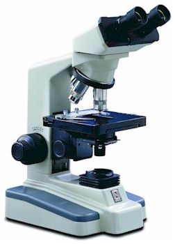
The Bright field compound microscope is a tool commonly used by thousands of
scientists and students in many different fields of study. It is used
to provide fine details of magnified images for the object being viewed.
The high quality image is due to complex calculations of light rays
travelling through the many lens systems within the microscope. This web page
is going to dissect the pathway of the light source and describe the how the
magnified images are viewed.
Some basic facts about light
The Components of a microscope
The Objective Lens System
The Ocular System
The Condenser
References
Simple facts on light
Light travels in light waves. A light wave is propagated as an oscillation of electrons in electric and magnetic fields. The two fields travel in the same direction, and can be defined as a sin graph.
The velocity of light is slower in the presence of matter. This velocity depends on the properties of the material, and on the frequency of the wave.
Colors have different wave frequencies. This allows the eye to see different colors.
Colors have different wave frequencies. This allows the eye to see different colors.
| Color |
Frequency |
| RED |
384-482 |
| Orange |
482-503 |
| Yellow |
503-520 |
| Green |
520-610 |
| Blue |
610-659 |
| Violet |
659-769 |
When pure white light, a combination of the all the colors, hits a lens
the different colors refract at different angels. This is due to the
different frequencies of the different colors. Take red and blue light
for example. Red light has a higher frequency so it travels less than the
blue light in the lens. Then when it comes out of the lens the red light will
refract further away from the lens then the blue light will.
This is an example of Chromatic aberration - where a lens cannot focus all the colors to
the same point.
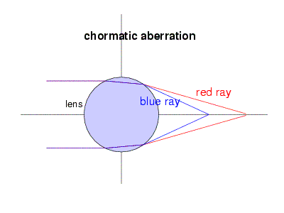
This is corrected by adding a second, negative, lens next to the first lens The negative lens cancels out the errors in chromatic aberration and focuses all the colors together.

The components of a microscope
The compound microscope consists of two major ray-tracing systems:
The optical components consisting of image forming and image producing lens system; and a lens system, which concentrated light on the object.
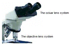
The "objective lens system" is located at the lower end of the tube and
the eyepiece, or "ocular system" at the upper end of the tube.
The objective system produces an enlarged, real image of the object, which is further enlarged by the ocular system.
The condenser system is responsible for the amount of light being placed on the object. This is a lens system but is not directly involved with the image formation although
combined with the optical components the microscope produces the fine detailed images of the objects being viewed.
There are other mechanical components such as the microscope stand, base, limb and arm, which support the lens systems.
The Objective Lens System
The objective lens system receives light from the object and projects an image near the top of the tube.
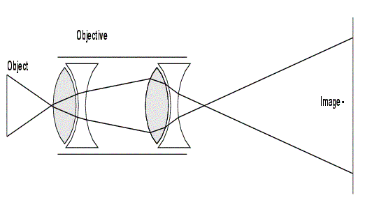
The objective is the most critical of the two lens systems and the microscopes are designed
so that the objective can be used at its maximum efficiency.
The image produced at the top of the tube is the image that is viewed through the ocular system.
The simplest and cheapest of objective lens systems can be made up of just 2 lenses but of course
these systems will produce lower quality images.
 The microscope is usually equipped with a number of objectives.
Each objective is engraved with information about its features.
Magnification Factor of the objective:
In the example shown the “40” indicates the ratio between the original object size and the image produced by the objective.
Objectives normally come in powers of 4X, 10X, 20X, 40X, 50X, and 100X.
Numerical Aperture of the Objective:
0.65 in the diagram represents the Numerical aperture. This number indicates the "light gathering" ability of the objective and its
resolving power. Lower numerical aperture numbers relate to lower power objectives and higher numbers are found in objectives of higher magnifying power.
Tube Length
Objectives are designed to be for a certain tube length. In the diagram, “160” indicates this. The standard tube length has been established as 160 mm, although different tube lengths exist for different viewing purposes.
The tube length plays an important role in the magnification. With the objective on one end of the tube and the oculars on the other end, the greater the distance between the two, the higher magnification is achieved.
Cover Glass Thickness
The thickness of the cover glass is also taken in to consideration for viewing purposes. In the example “0.17” indicates the thickness, in millimetres which should be used on the object.
The cover glass is essentially the first lens of the objective system and its effect on the path of light is critical. If the appropriate cover glass is not used then the result will be the inability to focus the object.
Optical correction
The term "Plan" on the example objective indicates the optical correction contained in the objective. There are certain aberrations in lens systems such as chromatic aberration, which was discussed above.
The aberrations are corrected to a certain degree but cannot be perfectly corrected. Thus higher level of correction in the objectives are much more expensive.
The Ocular System
The objective receives light from the object and forms and enlarged image of it near the top of the tube. This image is extends into the second lens system, the ocular or “eyepiece”. The image is further magnified by the eyepiece and is projected to the eye of the observer.
The ocular is placed at the top of the tube so that its focal plane coincides with the plane of the image being produced by the objective. The eyepieces are much simpler than objectives but are equally as important for high quality images.
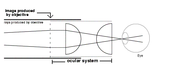
One commonly used eyepiece is the Ramsden ocular. It is made up of two compound lenses, with the convex surfaces facing each other. In the Ramsden design the diaphragm is located in front of the field lens.
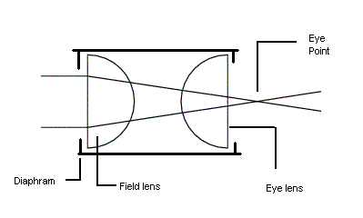
The design of the Ramsden ocular allows the eye point to be 12mm from the end of the eyepiece. As a result, this gives a comfortable position for the observer.
The overall magnification of a microscope with a 160mm tube can be easily calculated by multiplying the magnification factor of the objective by the magnification factor of the ocular.
Objective X x Ocular X = Magnification
For example, a 40X objective used with a 10X ocular will have a magnification of 400X.
If the tube length exceeds the standard 160mm then the magnifcation will be higher. For example the magnification of a 200mm tube length will is calculated by the following formula:
200/160 X 40 X 10 = 500X
The Condenser
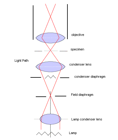
The condenser is the third lens system in the compound microscope. It receives light from the light source and is responsible for the concentration of light rays on the object. The condenser produces the light that is received by the objective lens. Thus the objective and the condenser must be optically compatible. If the condenser was to produce a beam of light that was too narrow the object would not illuminate properly and the image would appear dim. If the beam of light was too wide the image would appear very bright and the details would be very poor.
A condenser that produced a constant beam of light would be of no use so it must be variable. It has an adjustable diameter to allow the desired amount of light. The condenser also has a vertical adjustment, which is controlled by a knob on the side of the microscope. Proper alignment of the condenser will ensure that the beam of light fully illuminates the object.
References
Daniel Malacara, "Physical Optics and Light Measurents", Academic Press,INC. 1988
Horst Piller,"Microscope Photometry",Spinger-Verlag New York 1977
Savile Bradury"An introduction to the optical microscope"Oxford Press 1991
James S. Walker "Physics" Prentice Hall 2002
John Shigeta 77501997
math 309

