We take a brief look at some ways in which mirrors and lenses are utilised in technology.
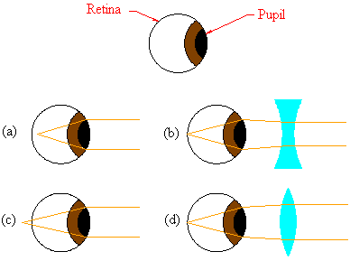
A greatly simplified view of the human eye is shown below. The pupil is a little hole which allows light to pass into the eye. Behind the pupil lies the eye's lens. Muscles in the eye control the size of the pupil and the shape of the lens, thereby adjusting the amount of light that enters they eye and the focus of the lens. The retina is a sensitive layer of nerves at the back of the eyeball; incident light upon the retina is translated into a coherent image by the brain.

Many people do not have perfect vision; that is, a lot of people have eyes whose lenses do not focus light properly on the retina. Two well-known vision problems correctible via eyeglasses are nearsightedness (picture (a) above) and farsightedness (picture (c)). Nearsightedness focusses rays of light in front of the retina, while farsightedness focusses rays behind the retina. A diverging lens can correct nearsightedness by bending incoming light rays outwards, so that the eye's lens (which usually bends incoming rays too much) focusses the light closer to the retina (picture (b)). A converging lens similarly corrects farsightedness (picture (d))1.
In our study of lenses, we saw that if the source was placed within a focal length of a converging lens, the lens yielded a magnified image on the same side of the lens as the source. This is, of course, the detective's best friend, the magnifying glass.
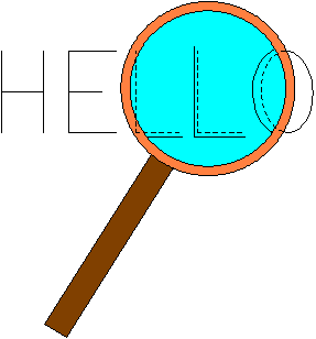
The amount of magnification, as we know from our treatment of lenses, depends on the distance of the source from the lens, and the refractive index of the lens material.
Cameras, unsurprisingly, work on similar principles as the eye.
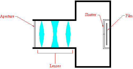
The aperture, which lets light into the inside of the camera, corresponds to the pupil. The system of lenses in a camera performs the same function as the lens of the eye. However, whereas the lens of the eye changes shape to change focus, glass lenses are not very forgiving of shape changes. Instead, the lens system can be slid along its optical axis in order to focus on the film. Of course, the film plays the role of the retina. In addition, cameras have a shutter, which opens and closes quickly so that the film does not get inundated with light. This produces a more or less clear image of the instant that the photographer shoots.
Simple microscopes use lens systems to magnify very small objects, as illustrated in the following diagram.
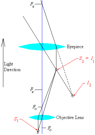
An object (S1) too small to examine with the naked eye is placed just outside the focus Fo of the objective lens in the microscope above. Tracing the infinite and central rays as we have before, we can find the location of the image I1. We know that a source within the focal length of a converging lens will result in an enlarged virtual image; hence if we position the eyepiece of the microscope so that its focus overreaches I1, the final image seen (I2) will be a magnified image.
The shrewd reader will notice that our simple microscope gives an inverted image, which could be inconvenient for certain situations. This problem can be solved by using a different lens arrangement, as shown below.

The colouring above is meant to help the reader to identify which components the labellings refer to. Our microscope consists of three converging lenses. From our pictorial treatment of lenses, we know that a source between one and two focal lengths of a converging lens gives a magnified and inverted image. Thus, we put the source somewhere within this magic region for Lens A, and figure out where the image will land using ray tracing. Knowing where the first image lands, we place a second converging lens, B, so that the first image falls between one and two focal lengths for Lens B. Finally, we can employ ray tracing to discover the position of the second image. After interacting with lens B, the source point has been magnified twice, and inverted twice, so it is upright. We place Lens C so that the second image falls within one focal length of C. As we know, such an arrangement will produce a magnified, upright, virtual image, as illustrated.
Telescopes serve much the same purpose as microscopes; both magnify what the user wishes to observe. The difference is that microscopes are supposed to be used to examine small objects that are close to the objective lens, while telescopes are supposed to be used to examine objects that are very far away (in many cases, extra-terrestrial). For historical purposes, we include a diagram of Galileo's telescope here.
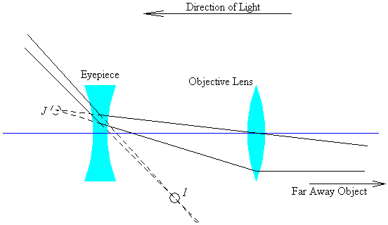
J is the image point that would have been seen had the diverging eyepiece not been inserted between the objective lens and J. The image point I is actually seen when one peers through the eyepiece.
Of course, just like with microscopes, much more complicated lens systems can be utilised, resulting in greater magnification, and thus finer detail.
All of the applications we have looked at so far are dominated by the refractive half of our axioms of optics. This might lead to the unwarranted conclusion that reflection plays little or no role at all in technology. In the next and last leg of our journey together in optics, we will have reason to mention the reflecting telescope, which uses mirrors to focus light from far away objects for study. Here, we consider CDs.
Without straying too far into the milieu of computer science, we can say that all a computer really understands is 0s and 1s. The Law of Reflection gives a relatively easy way of storing and reading these digits.
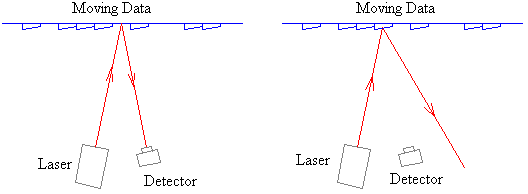
A CD is basically a highly reflective surface that is filled with bumps and valleys. A laser is placed somewhere in the player's casing, and a device capable of detecting a light source is placed so that the laser's rays will be reflected into the device when the laser is aimed at a valley. The peaks are arranged so that the laser's rays reflecting off the peaks will miss the detector completely. The detector registers 0s and 1s appropriately, when it detects the absence or presence of light.
The lens and detector are allowed to move radially, whereas the CD is allowed to spin. This offers a momentous improvement over tape devices for audio, and floppy disks for computer storage. Audio tapes are sequential access devices; data in the middle cannot be accessed directly, instead the intervening data from the beginning to the point of interest must be "fast-forwarded." This can be a very slow process. CDs (which could also be thought of as sequential access devices, in a way) have a lot of freedom in the sense that their spin and the movement of the lens-detector system allows very quick access to data anywhere on the disc. Floppy disks are magnetic media; as such they must be kept away from magnetic fields if the data they contain are to maintain integrity. CDs, as optical media, do not suffer such a limitation.
The size of the peaks and valleys of optical media dictate the storage capacity -- smaller shapes means more data can fit on the disc. While the problem of minimising the size of the peaks and valleys is a manufacturing problem, ironically, we are not free of optics. Lasers are generally the only instruments that are fine enough to chisel the microscopic shapes accurately.