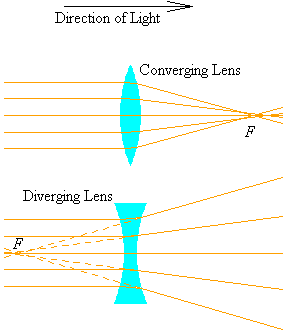
In this section, we will discuss lenses, after which we should have enough theoretical knowledge to speak of some applications of optical systems, and difficulties that arise from their use.
The lenses that we will discuss will be thin, in the sense that their widths are small enough that we can basically ignore the behaviour of the rays inside the lenses, except for refraction at the surfaces. Also, assuming slimness allows us to make measurements of radii, foci, and source and image points independent of the side of the lens that we are interested in.
Lenses are classified as one of two types, converging and diverging.

A converging lens focusses rays from infinity so that they intersect at a common point, more or less. A diverging lens bends rays from infinity so that it seems that they originate from the same point. In either case, we refer to the point of convergence or divergence as the focus of the lens.
In our diagrams, we will generally use two convex surfaces to denote a converging lens, and two concave surfaces to denote a diverging lens1.
In order to develop theory for thin lenses, we need to adopt a convention about how to refer to the two different surfaces of a lens, because the final image formed by the lens depends on the interaction of the source object with each surface of the lens.
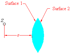
Given a source point S (whose image we want to find), we define Surface 1 as the surface of the lens on the side that the source lies. Surface 2 is the surface opposite to the source. Distances, though measured from the nearest surface of the lens, will be independent of the sides because of our assumption of thinness.
Consider a lens of index n2 surrounded by some uniform material with index n1. Although in the diagrams that follow, the lens is of the convergent type, the formulas are equally valid for diverging lenses when we utilise our sign conventions.
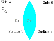
Now, from our development of refraction at spherical surfaces, we can find the image of the source point with respect to interaction with Surface 1. We know that the positions of the source and image satisfy

where we have used subscripts for R, s and i to denote interaction with the first surface of the lens.
The key observation at this point is that the image point i1 acts as the source point s2 for the interaction with the second surface of the lens. Applying our knowledge of spherical refraction yet again, we get

where we have been careful to switch the indices, as we are now travelling from the lens to the surrounding region. We have also substituted i1 for s2, but with a minus sign. This can be explained via our sign conventions. A priori, we do not know which side of the lens the first image will land on. If i1 is positive, then in our diagram, it is to the right of Surface 1. Hence, by our thin lens assumption, the first image point is also to the right of Surface 2. The first image point is defined to be the second source point, which we now know is on the side to which light passes. By our sign conventions, s2 must be negative, so we must tack on a negative sign to i1 when we make our substitution. If i1 is negative, then it is to the left of Surface 1 (Surface 2), and so is our new source point. The source is positive by our sign conventions, so we again need to tack on a negative sign. In either case, we must take the negative in making our substitution, so the move is valid.
Substitution of our 1/i1 result for interaction with Surface 1 into the equation for interaction with Surface 2 yields

where we have simplified using s to denote the object position and i to denote the final image position.
If we let n1 = 1 and n2 = n (i.e. we have a glass lens of some index in air), then we get a fairly accurate way of predicting the location of images.

This result is called the lens-makers' equation. The sharp reader will notice the striking similarity between this equation and the position equation for mirrors. In fact, as we let s get larger and larger, its reciprocal tends to zero, and we can find the focus of the lens in air.

For the rest of our discussion, we will be working with lenses in air; this is the case that applies for the applications we will look at, and it is conceptually easier to carry around a single index n anyway.
We close our discussion of image positions with an observation. The equation

is symmetric, in the sense that if we move the source to the other side of the lens and shine light from the source's side, the focus is exactly the same. (This shows that a lens has two foci, on on each side of the lens, with equal distance to the lens.) This symmetry is most easily seen from the lens-makers' equation.
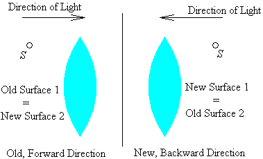
Reversing the direction of travel is equivalent to switching the roles of the radii R1 and R2 in the lens-makers' equation. However, the signs of R1, R2 are now the reverse of what they were when the light travelled "forward." This is because of our sign conventions; Sides A and B have swapped places. Thus, when we go forward, the lens-makers' equation gives the quantity 1/R1 a positive sign, and when we go backward, the equation gives the quantity 1/R1 a negative sign, but R1 is now the negative of what it was going forward. In essence, we are applying a double negative, and they cancel. A similar result holds for R2.
Finding the magnification of a thin lens is simple. We need only to trace two rays from a source point, and find their intersection, then use similar triangles as we did with mirrors. We will use a ray from infinity, and a ray that goes through the physical centre of the lens.

The ray from infinity crosses the focus; assuming that the thin lens acts as if incoming rays are bent at the middle of the lens, we can easily find the locus any incoming ray parallel to the optical axis. After making a simplification, the ray through the centre of the lens is also easy. Since the lens is thin, a ray that goes through the centre of the lens will act very much like it is hitting a flat plane of glass. In our treatment of Snell's Law, we saw that a ray hitting a flat plane of glass was displaced, but did not change direction. Since our lens is thin, the displacement will be very small, and we can assume that a ray going through the centre continues on as if not refracted at all. Now, the magnification is of course the ratio of the heights of the image to the source; from our development of the positions of sources and images we see that the familiar result M = -i/s holds.
The facts presented in this subsection are readily verified using the source-image and magnification equations developed above. The distance from the lens to the foci F and F' are equal.
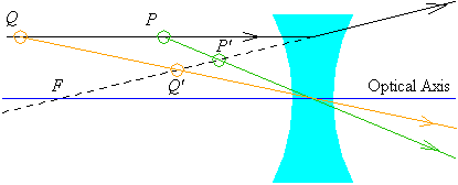
For a diverging lens, the image is always virtual, diminished, and upright, as illustrated in the following diagram.
Converging lenses are divided into three cases, which depend on the source location.
If the source is more than two focal lengths away from the lens,
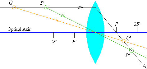
we see that the image is inverted, diminished, and real.
If the source is between one and two focal lengths away from the lens,
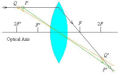
the image is magnified, and is again real and inverted.
For a source that is within one focal length of a converging lens,
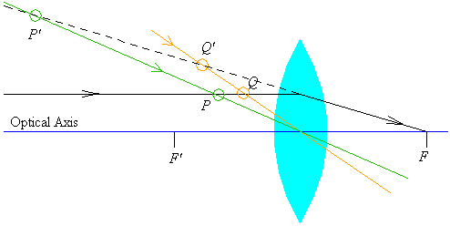
the image is virtual, right side up, and magnified.