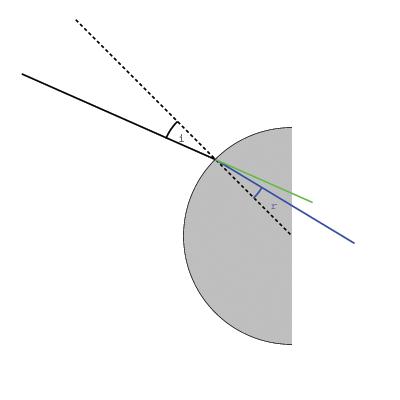
When tracing the ray through the
different interfaces, the same fomula is used over and over again. This
generates the pictures as they were used in the project.
Lens Shapes
In order to simplfy the calculations
for this project, the lens that were used (both the eye and the
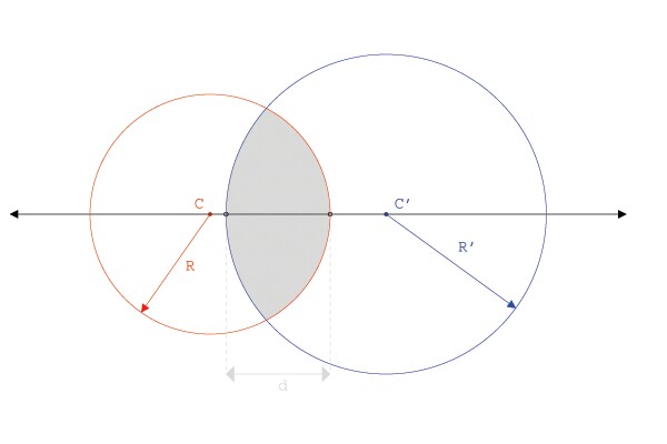
corrective lens) are assumed to be spherical. A spherical lens is formed
in the following way:
The lens has two surfaces, both of which
can be approximated as being the soild that results from the
intersection of two spheres. The two intersecting spheres, with radii R
and R' have two centers located at C and C' respectively. In the next
section, we will discuss how variations in the distance between C and C'
effect the distance, d, and the effect it has on lens focusing.
Introduction
Colour Vision
Colour Math
Approximations
Focal Lengths and Distances
GRIN Systems
Human Vision
Vision Problems
Corrections
Introduction
Colour Vision
Colour Math
Approximations
Focal Lengths and Distances
GRIN Systems
Human Vision
Vision Problems
Corrections
